Features
Rated working pressure: 21 MPa
Heat resistance: 120℃
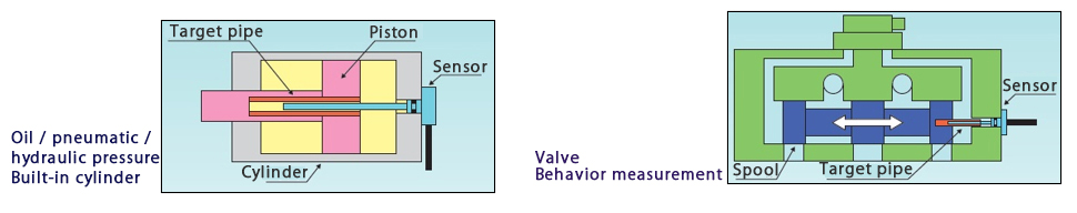
Can be built into hydraulic (oil) pressure / pneumatic / aqua (water pressure) cylinders
Custom orders starting from one unit accepted.
Model
| LP | 40 | – | 050 | – | LFH | – | 1 |
|---|---|---|---|---|---|---|---|
| ① | ② | ③ | ④ | ⑤ |
| ① | Model classification | LP | : | Linear Pulse Coder |
| ② | Sensor diameter (mm) | 40 | : | φ4.0 |
| ③ | Measuring range (mm) | 050 | : | 50 |
| ④ | Shape of mounting part | LFH | : | Flange |
| R8H | : | M8 screw | ||
| ⑤ | Amplifier | 1 | : | CV05 |
| 2 | : | CVS5 | 3 | : | CV06A | 4 | : | CV06D |
Specification
| Model | LP40-LFH/R8H | |
|---|---|---|
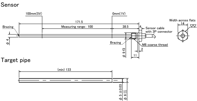
| Sensor diameter(mm) | φ4 | |
| Target | Material | Brass pipe(C2700) |
| Outer diameter(mm) | φ6(-0.01/-0.05) | |
| Inner diameter(mm) | φ5(±0.03) | |
| Linearity (mm) | ±2%/FS or less | |
| Temperature characteristics | ±2.6%/FS or less (0 to 80℃ @ center of measurement range) | |
| Operating temperature range(℃) | -10~80 | |
| Lead-out cable | Length(m) | 2 |
| Outer diameter(mm) | φ4.8 cross-linked PE coated shielded cable | |
| Protective structure | equivalent to IP64 | |
| Pressure resistance | 21 MPa (Pressure test: 35 MPa [10min]) | |
| Magnetic field resistance | 0.2T (Tesla) | |
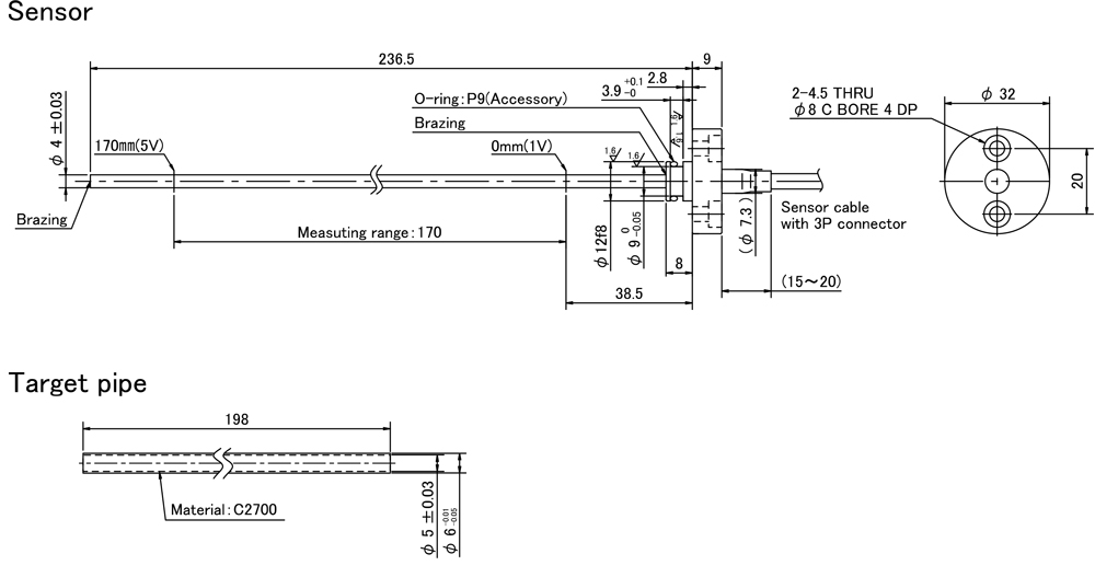
Outline drawing
LFH flange type (Cable pull-out direction : Vertical)
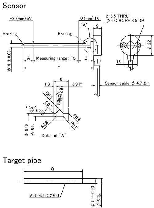
| (mm) | |||||
| Model | A | B | FS | L | Q |
|---|---|---|---|---|---|
| LP40-015-LFH | 20 | 16 | 15 | 51 | 45 |
| LP40-030-LFH | 30 | 66 | 60 | ||
| LP40-050-LFH | 50 | 86 | 80 | ||
| LP40-075-LFH | 75 | 111 | 105 | ||
| LP40-100-LFH | 100 | 136 | 130 | ||
| LP40-125-LFH | 125 | 161 | 155 | ||
| LP40-150-LFH | 40 | 30 | 150 | 220 | 200 |
| LP40-175-LFH | 60 | 175 | 265 | 245 | |
| LP40-200-LFH | 200 | 290 | 270 | ||
LFH flange type (Cable pull-out direction : Horizontal)
R8H screw type (LP40-100-R8H)
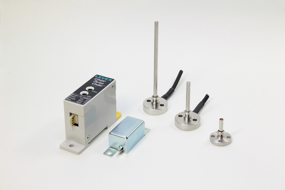
Application examples
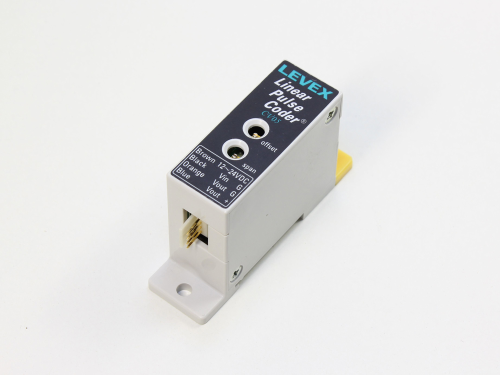
Amplifier
Specification
| Model | CV06A | CV06D | CV05 | CVS5 CVS5(Resin case type) |
|---|---|---|---|---|
| Power-supply voltage | DC12~24V ±10% | DC18~24V ±10% | DC12~24V ±10% | DC9~16V ±10% |
| Current consumption | 50mA or less | 100mA or less | 40mA or less | |
| Output voltage | Analog output DC1~5V | |||
| Resolution | Approx 1/2000 of measuring range | |||
| Responsiveness | About 4kHz(-3dB) | |||
| Operating temperature range | -20~80℃ (No condensation) | |||
| Temperature characteristics | 0.025%/FS or less (0 to 60℃ @ center of measurement range) | |||
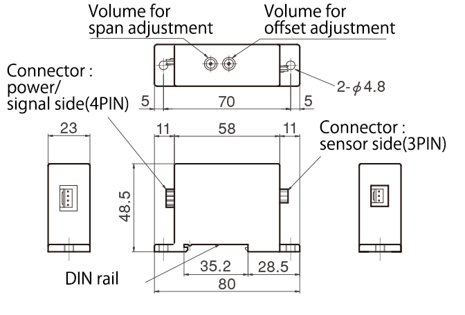
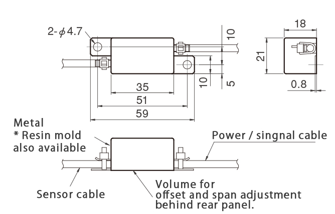
Outline drawing
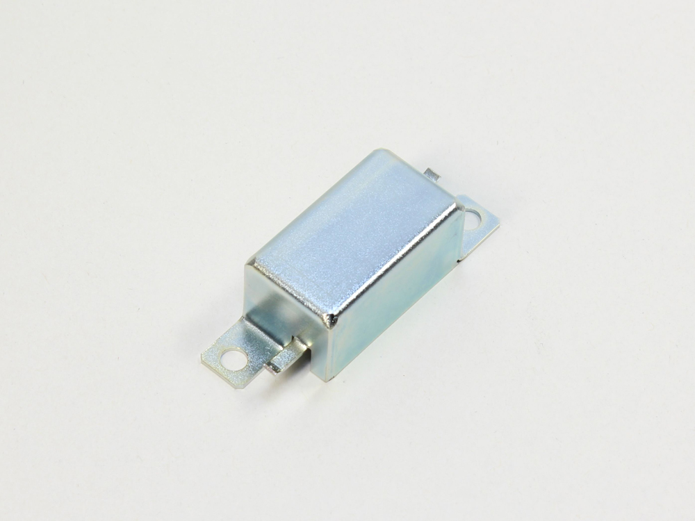
CV05
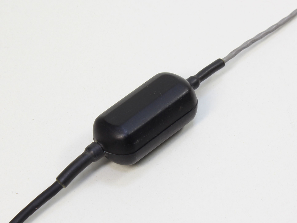
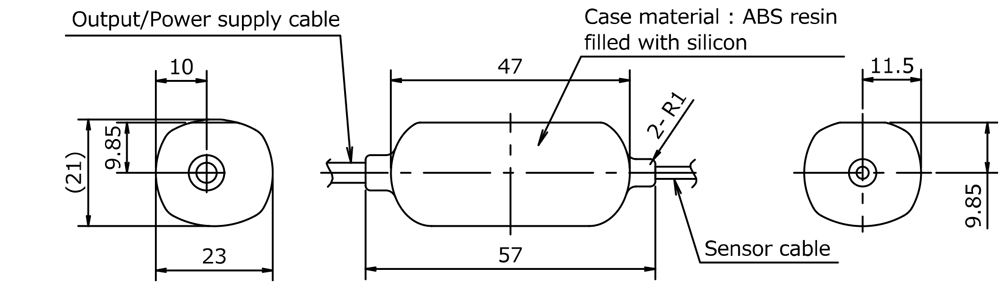
CVS5
CVS5(Built-in resin case type)
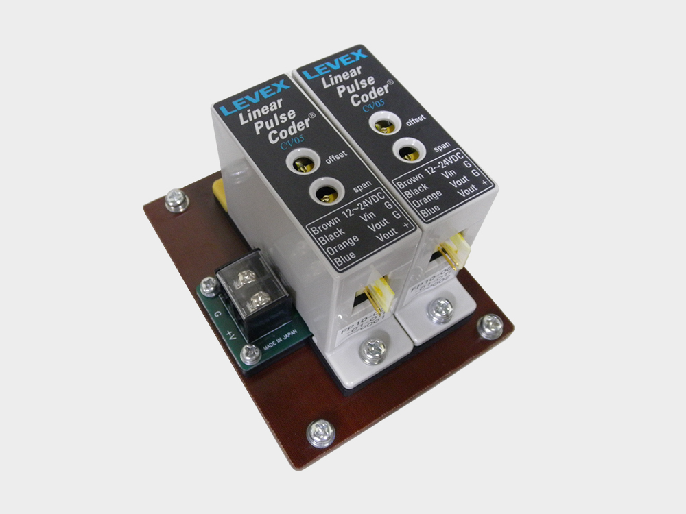
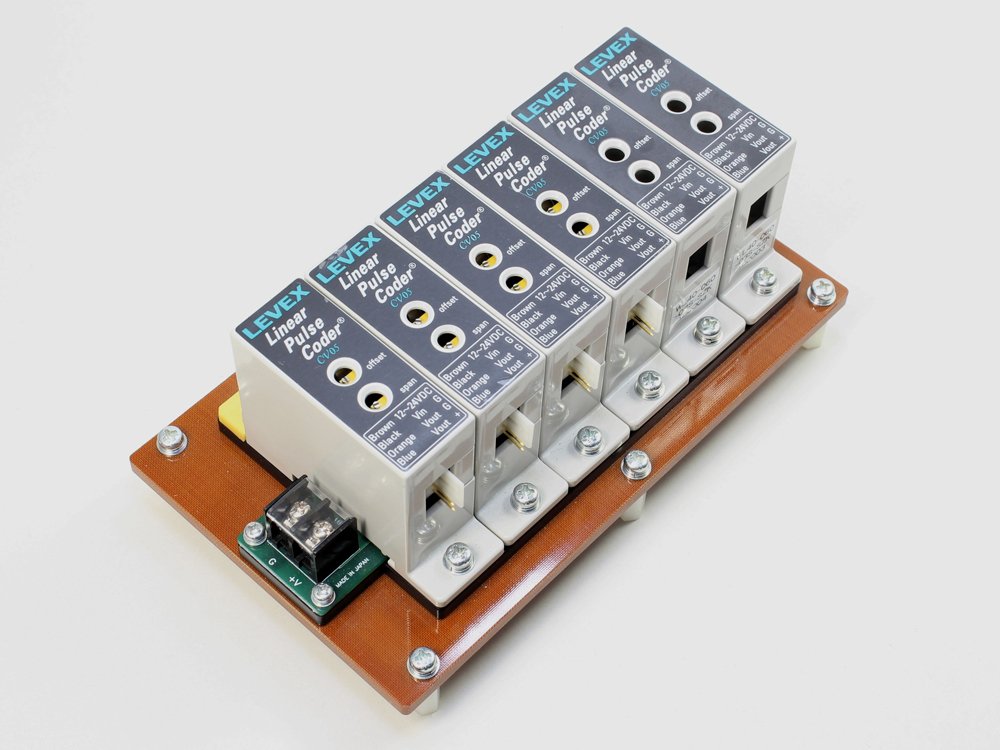
(Options) CV05 sync board
Purpose
When multiple sensors of the same type are used, periodic interference noise may occur in the output.
To counter this, noise is reduced by synchronizing the signal generation circuits in each amplifier.
To counter this, noise is reduced by synchronizing the signal generation circuits in each amplifier.
Lineup
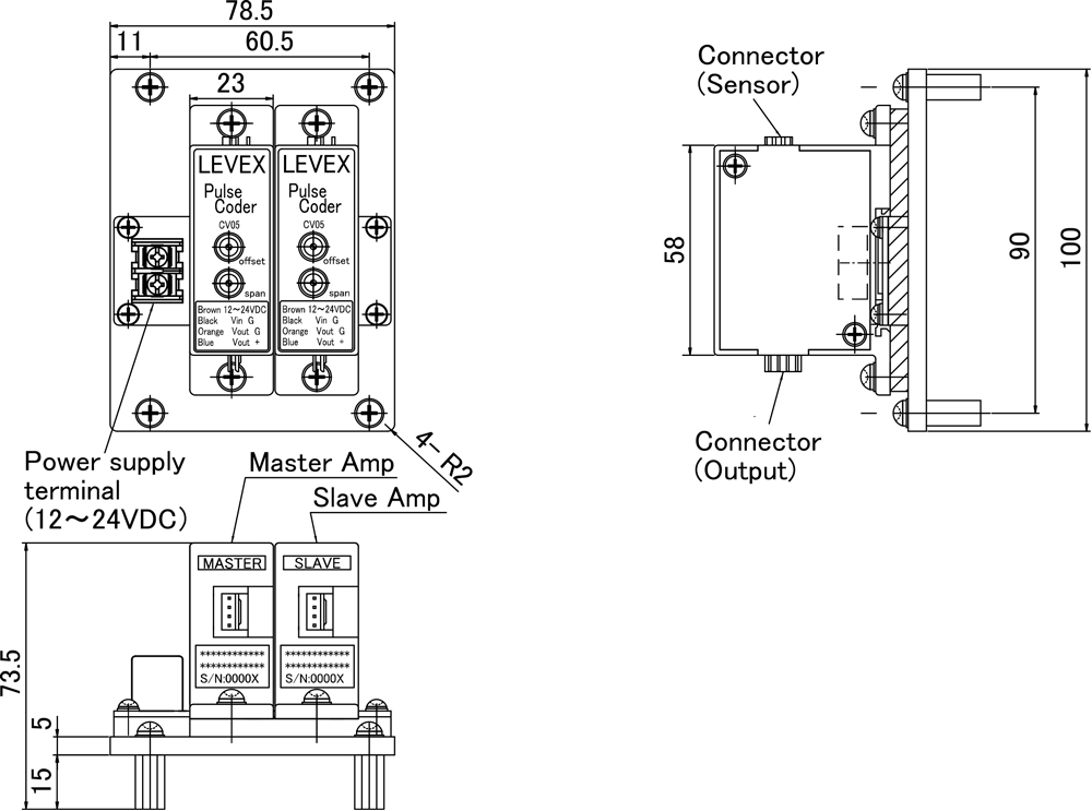
For 2 axes
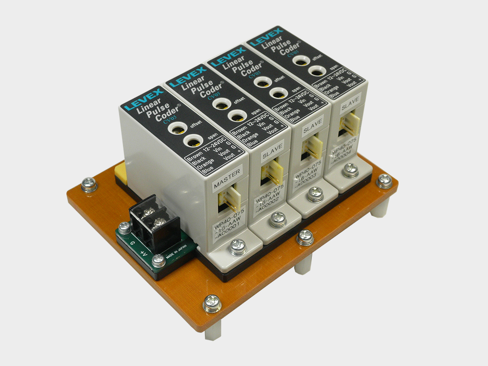
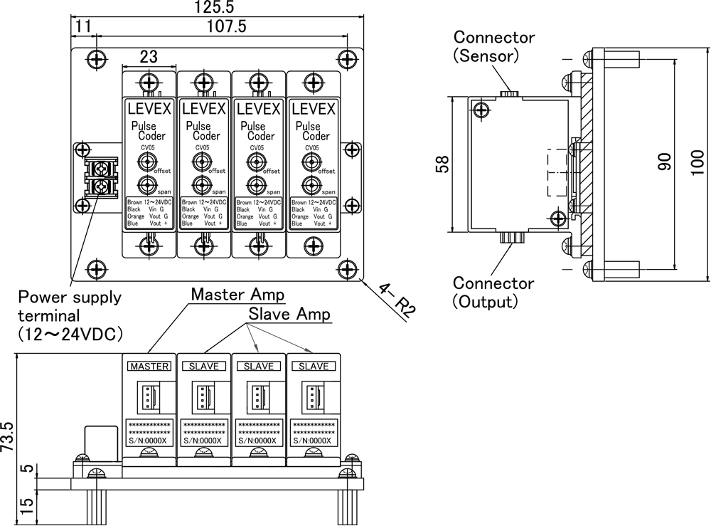
For 4 axes
For 6 axes
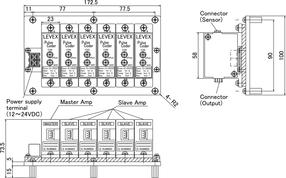
Precautions for use
– Only connect sensors and amplifiers with the same serial numbers.
– The master amplifier is fixed.
– Slave amplifiers do not operate in isolation.
– Operation with a reduced number of slave amps connected is possible if they are the same model.
– The master amplifier is fixed.
– Slave amplifiers do not operate in isolation.
– Operation with a reduced number of slave amps connected is possible if they are the same model.
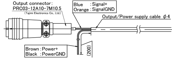
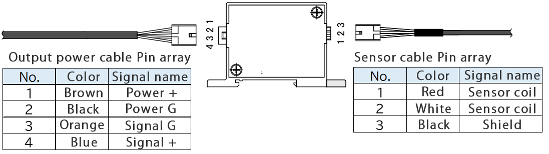
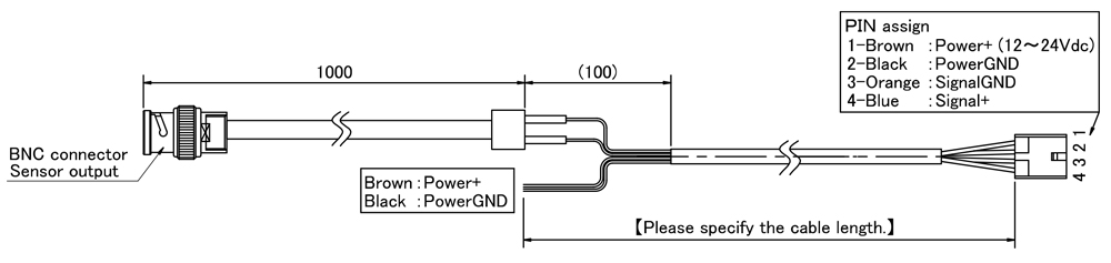
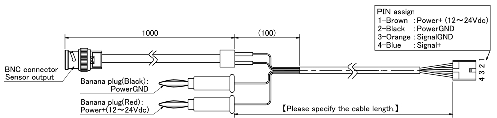
Output – power cable
Connection configuration
Standard
Cable: Dedicated 4-core cable (Length:2m)
End treatment – Amplifier side : With connector / Measuring instrument side : Unfinished
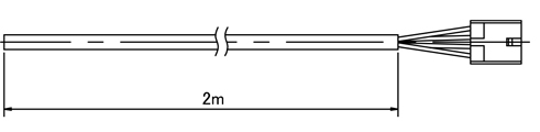
End treatment – Amplifier side : With connector / Measuring instrument side : Unfinished
(End treatment example) * We fit a range of connectors.
(Signal side) With BNC conversion cable
(Signal side) BNC conversion cable + (Power supply side) Banana plug
(Signal line) With Tajimi Electronics connector