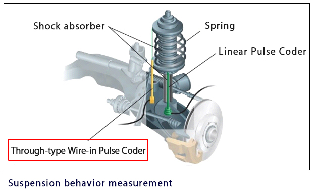
Features
Through-structure with the cable drawn out horizontally.
Diameter: φ5 makes fitting in places with no space possible.
Removing water, dust, etc. from the measurement unit
(inside the pipe) is easy.
(inside the pipe) is easy.
Target blockage during unexpected behavior can be avoided.
Custom orders starting from one unit available.
.png)
Model
| WPK | 50 | – | 100 | – | 06 | – | 1 |
|---|---|---|---|---|---|---|---|
| ① | ② | ③ | ④ | ⑤ |
| ① | Model classification | WPK | : | Wire-in Pulse Coder – Through-type |
| ② | Sensor diameter(mm) | 20 | : | φ2 |
| 50 | : | φ5 | ||
| ③ | Measuring range (mm) | 100 | : | 100 |
| 150 | : | 150 | ||
| 200 | : | 200 | ||
| ④ | Target wire diameter(mm) | 02 | : | φ0.2 |
| 06 | : | φ0.6 | ||
| ⑤ | Amplifier | 1 | : | CV05 |
| 2 | : | CVS5 | 3 | : | CV06A | 4 | : | CV06D |
Specification
| Model | WPK50 | WPK20 | |
|---|---|---|---|
| Sensor diameter (mm) | φ5 | φ2 | |
| Target | Material | SUS304 | |
| Outer diameter(mm) | φ0.6 | φ0.2 | |
| Linearity(mm) | 3.5%/FS or less | 5%/FS or less | |
| Temperature characteristics | 3%/FS or less (15 to 25℃ @ center of measuring range) |
5%/FS or less (15 to 25℃ @ center of measuring range) |
|
| Operating temperature range(℃) | -20~80℃ | ||
| Lead-out cable | Length (m) | 2 (Max.6m) | |
| Outer diameter | φ2.4 twisted pair cable | φ1.3 twisted pair cable | |
| Protective structure | equivalent to IP64 | ||
Outline drawing
Standard
WPK50
Sensor diameter:φ5㎜Target wire diameter:φ0.6㎜
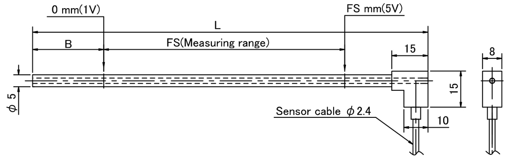
| (mm) | |||
| Model | B | FS | L |
|---|---|---|---|
| WPK50-100 | 29.5 | 100 | 164 |
| WPK50-150 | 34.5 | 150 | 217 |
| WPK50-200 | 35 | 200 | 275 |
| WPK50-250 | 19.5 | 250 | 292 |
| WPK50-300 | 19.5 | 300 | 342 |
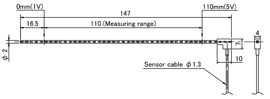
WPK20-110
Sensor diameter:φ2mmTarget wire diameter:φ0.2mm
Measuring range:110mm
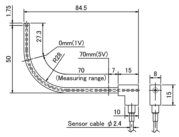
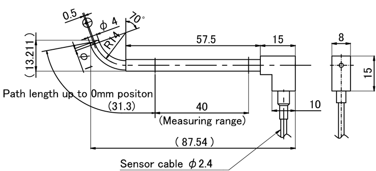
Special type
WLK40-070 (Measuring range:70mm)
WJK50-040 (Measuring range:40mm)
Application examples
Amplifier
Specification
| Model | CV06A | CV06D | CV05 | CVS5 CVS5(Resin case type) |
|---|---|---|---|---|
| Power-supply voltage | DC12~24V ±10% | DC18~24V ±10% | DC12~24V ±10% | DC9~16V ±10% |
| Current consumption | 50mA or less | 100mA or less | 40mA or less | |
| Output voltage | Analog output DC1~5V | |||
| Resolution | Approx 1/2000 of measuring range | |||
| Responsiveness | About 4kHz(-3dB) | |||
| Operating temperature range | -20~80℃ (No condensation) | |||
| Temperature characteristics | 0.025%/FS or less (0 to 60℃ @ center of measurement range) | |||
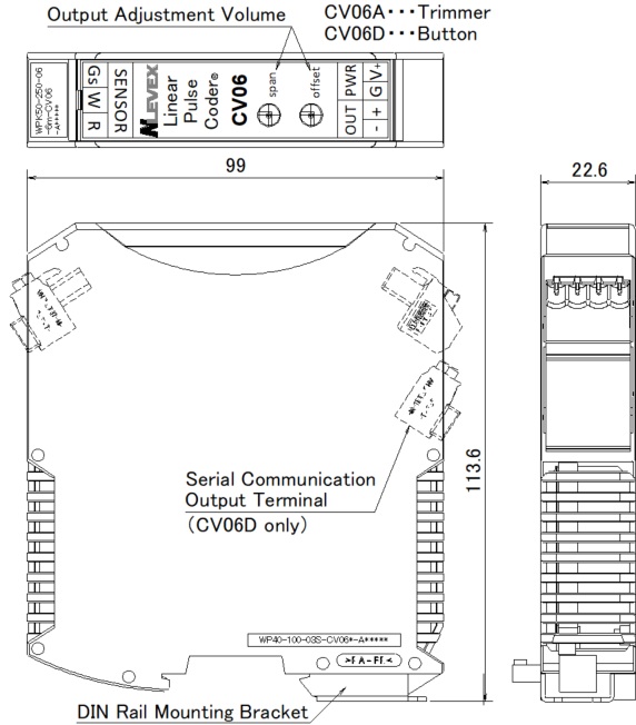
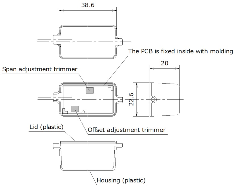
Outline drawing
CV06A/CV06D
CV06新_0N2A9201-Photoroom.png)
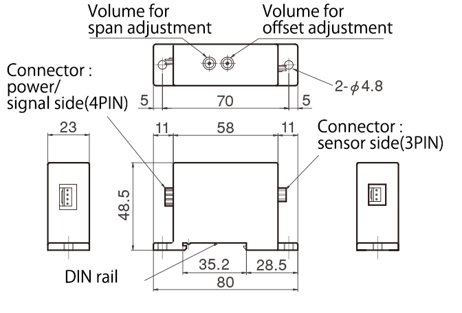
CV05
CV05新_0N2A9211-Photoroom.png)
CVS5
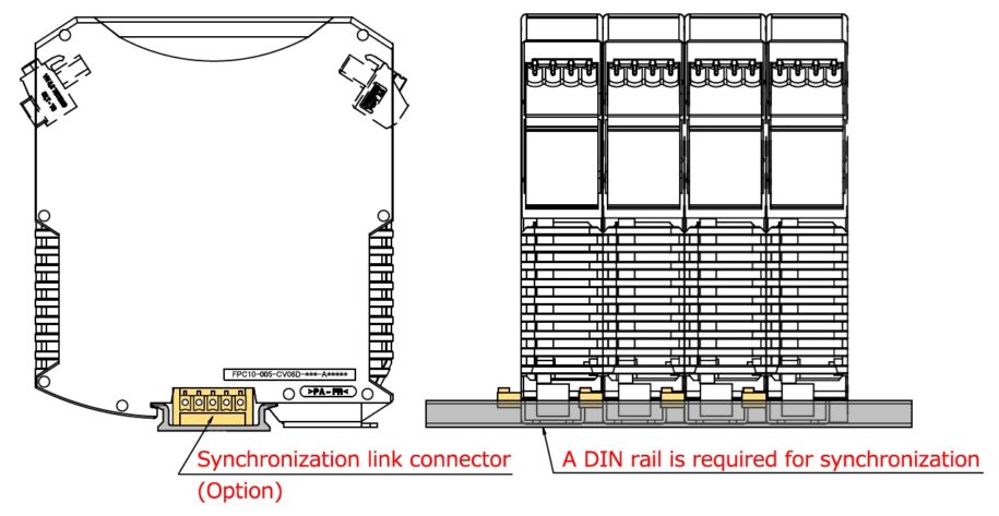
(Options) Synchronous processing
Purpose
When multiple sensors of the same type are used, periodic interference noise may occur in the output.
To counter this, noise is reduced by synchronizing the signal generation circuits in each amplifier.
To counter this, noise is reduced by synchronizing the signal generation circuits in each amplifier.
Synchronizable amplifier
CV06A
CV06D
CV06D
Synchronization method
Using a dedicated synchronization connector (on DIN rail)
Precautions for use
– Only connect sensors and amplifiers with the same serial numbers.
– The master amplifier is fixed.
– Slave amplifiers do not operate in isolation.
– Operation with a reduced number of slave amps connected is possible if they are the same model.
– Each amplifier requires a power supply.
– The master amplifier is fixed.
– Slave amplifiers do not operate in isolation.
– Operation with a reduced number of slave amps connected is possible if they are the same model.
– Each amplifier requires a power supply.
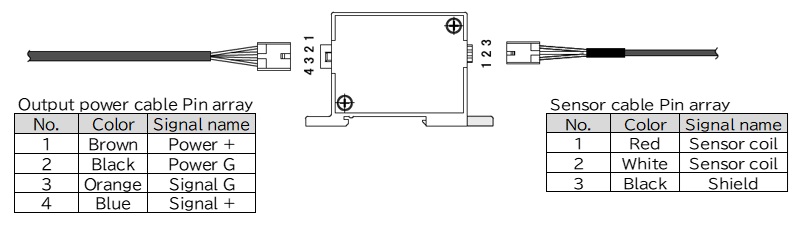
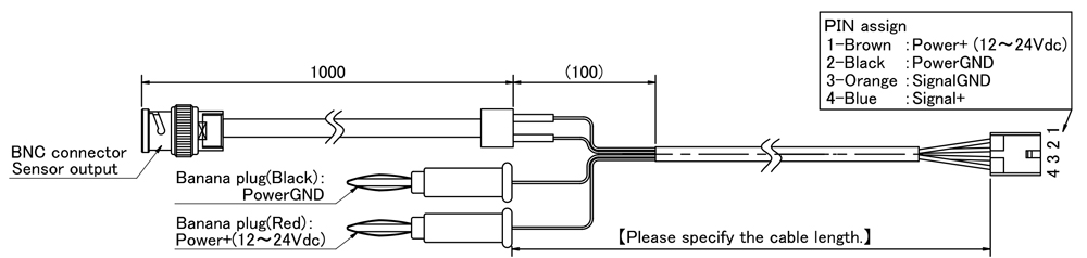
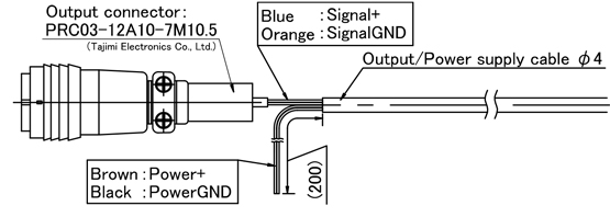
Output – power cable
Connection configuration
CV06A/CV06D
_NLVX_250218.jpg)
CV05
(End treatment example) * We fit a range of connectors.
(Signal side) With BNC conversion cable
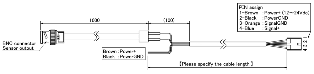
(Signal side) BNC conversion cable + (Power supply side) Banana plug
(Signal line) With Tajimi Electronics connector
Small absolute Sensor Inquiry
エラー: コンタクトフォームが見つかりません。